Any wood chip or pellet boiler no matter how good can be undone by an incorrectly designed fuel feeding system. Fuel feeding systems can be broadly assigned to one of the three basic categories below.

Pellet fuel is approximately three times the density of wood chips and is far easier to move from the fuel store to the boiler thanks to its flow characteristics. Pellets will flow down a smooth sloping surface at a 50 degree angle. As such, incorporating a pellet store in to an existing or new building is relatively simple. In addition, a wide variety of existing outdoor and indoor agricultural silos and stores are suitable for use with wood pellets. At this point the similarity with the agricultural industry ends. Augers specifically designed to move wood pellets are carefully engineered to convey the fuel at a suitable speed (they are geared to match the boiler size they are serving). Many of the flexible auger products on the market are in fact agricultural products originally designed to transport other more free flowing substances such as grain at maximum speed. High rotational speed causes mechanical damage to pellets, which can result in excessive dust levels, and blocked augers. In general, flexible augers should only be specified for systems where the auger has a single gravity fed pick up point (eg. the outlet from a conical silo). For large boilers (>400kw), flexible augers are generally unsuitable due to the required torque. rigid augers such as those commonly used for transporting wood chips are a far more robust solution.
Woodchips are very prone to 'bridging' augers, and they can form piles with vertical sides. Therefore, all wood chip feeding solutions require some form of mechanical agitation within the fuel store. If an auger is used without an agitating mechanism, the wood chips immediately around the auger will be successfully conveyed to the boiler, but new product will not fall into the auger. This process is known as 'bridging'. Propensity of a fuel towards bridging is a function of both moisture content and size specification of the fuel. For example, recycled fuels tend to be shredded rather than chipped - shredded fuels contain a high proportion of long splinter like pieces and therefore bridge far more than virgin round wood fuel produced with a chipper, which has on average a roughly square cross sectional area.

The simplest mechanical agitating mechanism is commonly known as a spring agitator, and consist of a pair of multi leafed sprung steel arms connected to a rotating disk with a 90 degree gearbox normally driven from the fuel extraction auger. As such, whenever the auger runs and starts to remove fuel, the sprung steel arms rotate over the auger and destroy the bridge. Various refinements exist, for example when using larger boilers (>400kw) it is normal for the spring agitator to have a separate drive shaft and motor to that of the feeding auger. In some cases, a single agitator mechanism is used to feed fuel into two augers in a twin boiler system. Spring agitator mechanism should not be used with fuels over G50 or W35, or where total boiler power feeding from a single agitator exceeds 800kW. If the boiler is required to burn recycled wood chips, spring agitators are generally unsuitable. Some systems require adjustments, such as altering the size of the opening in the auger casing, or adjusting the rotation speed of the agitator, to suit the flow characteristics of the fuel. Significant changes in fuel can result in a jammed auger and may require the fuel store to be emptied, particularly in systems where the extraction auger is completely open within the fuel store. Some manufacturers produce an alternative spring loaded articulated arm, which is more rigid than the sprung steel variant and can break up bridges in more difficult fuels. Because the agitator mechanism requires a fine grade of wood chip with a low moisture content, (which can be transported by augers over distances of up to 9m in a single auger with a rising angle of up to 45 degrees) the use of subterranean fuel stores up to 6m in depth is suitable for spring agitator systems. This allows direct discharge of the delivery vehicles load to the fuel store without any handling requirement on site.

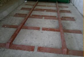
Sometimes referred to as walking floors, scraper floors are the most robust and flexible feeding system available. Fuel up to W60 and G100 can be fed without issue to a suitable extraction auger, chain conveyer, or hydraulic feeder. Typically, the scraper floor system consists of two or more rails approximately 1.5m in width and up to 10m in length. Each rail has triangular sections fixed at intervals which allow the rail to slide underneath the fuel in one direction, and then convey the pile of fuel on mass with the return stroke. Fuel is pulled to one end of the walking floor and through a letter box type opening in the base of a dividing wall, where it drops into a trough incorporating light barrier or capacitive level sensing, which controls the movement of the scraper floor. Very large systems further increase reliability by using additional hydraulic ram feeders to carry out final delivery of the fuel to the boiler, ensuring the entire feeding system is capable of handling G100 and W60 fuel. Even large frozen lumps of wood chips can be conveyed by the scraper floor and are cut using choppers built into the final hydraulic feeder. The use of long or steep 'rising' augers, such as those utilised to transport fuel from subterranean spring agitator equipped fuel stores, is not possible where G100 or fuel over W35 is specified. As scraper floor systems are typically reserved for 'walking floor' type boilers with the tolerance to burn these fuels, the fuel store is normally required to be at the same level or higher than the plant room floor level. Filling of a walking floor is typically via a front end loader such as a telehandler, as such it is not required to be able to tip from the delivery vehicle directly to a subterranean store.